

PARA DYNAMICS 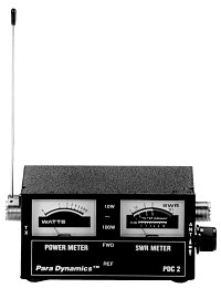
SWR METER INSTRUCTIONS
3-FUNCTION TEST INSTRUMENT – MODEL PDC 2
Introduction
Model PDC 2 test instrument is a compact 3-function test meter designed to indicate the condition of any 52 ohm antenna and antenna coax used for Citizens Band radio operation by testing or Standing Wave Ratio, relative RF power, or field strength. Tuning of transmitter can be accomplished when using this meter as a field strength meter. Also, comparing antennas can be accomplished with this meter. It is designed to be used for base stations or mobile operations
and can be permanently installed in the antenna system without any measurable loss of power.
Specifications
SWR 1:1 to 3:1
RF Power 0- 10 watts
0- 100 watts
Impedance 52 ohms
Accuracy SWR 5%
RF Power 10%
Meter 100-250 micro-amp DC
Connectors S0-239
Size 120(W)x60(H)x65(D) m/m
Weight 410g
SWR Function
The SWR Function of the test instrument is probably the most useful test performed. Testing for the SWR of Standing Wave Ratio provides the operator of the transmitter a good indication of the condition of his antenna and antenna lead cable since most antennas are located externally of the transmitter. In order to get the maximum amount of power radiated from the antenna, the lead line or coax and the antenna should be matched to the transmitter. For this meter a 52 ohm match is required which includes most CB operations that use RG-58U or RG-8U coax. Because a perfect match is never achieved the amount of mismatch can be measured by measuring the amount of Standing Waves that exist in the coax or antenna feedline. Measuring the Standing Waves can be accomplished by sampling the forward “FWD” power and the reflected “REF” power and comparing them and then expressing this difference as a ratio of reflected power to forward power. The following ratios are examples of the amount of power loss for a Standing Wave Ratio.
Power Loss SWR
0% = 1:1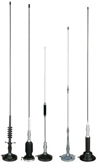
2% = 1:3:1
3% = 1:5:1
6% = 1:7:1
11% = 2:1
25% = 3:1
38% = 4:1
48% = 5:1
70% = 10:1
A ratio of 1.1:1 to a 2:1 is usually considered satisfactory for most operations.
Power Meter Function
The power meter function is provided to monitor the condition of the transmitter by measuring the relative RF power being generated in the transmitter. This meter will measure up to 100 watts of RF power with 10% accuracy. This is accomplished by sampling a small amount of RF energy from the transmission line. There will be no measurable power loss if the meter is left in the coax as a permanent installation.
 CAUTION: DO NOT TURN THE TRANSMITTER ON WHILE THE ANTENNA AND TEST METER ARE DISCONNECTED!
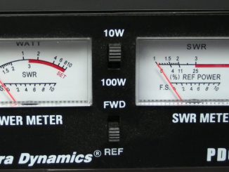
SWR Measurement
- With the meter properly connected and the transmitter off, place the slide switches on the SWR meter to the “FWD” positions.
- Place the SWR adjustment control on the SWR meter fully counter clockwise.
- Key the transmitter and adjust the SWR adjustment control for a full scale deflection to the “SET” mark on the meter.
- While the transmitter is on, place the “FWD-REF” switch to the “REF” or down position and read the SWR meter. This is the SWR
 NOTE: IF THE SWR IS ABOVE 2:1 THE ANTENNA MAY NEED TUNING OR THERE MAY BE A PROBLEM ON THE ANTENNA OR ANTENNA CABLE.
5. Several antennas provide a means for tuning by either slide adjustment or a control at the base. For sliding antennas, sliding 1/4″ each time and repeating the SWR measurement steps after each adjustment is usually a good method. First, moving the antenna inward and watching for an improvement in the SWR; then, outward if no improvement is noticed. For Citizens Band operation, tuning your antenna to one of the center channels will usually provide for the best SWR over the entire band. Use channel 20.
Power Measurement
 CAUTION: DO NOT TURN THE TRANSMITTER ON WHILE THE ANTENNA AND THE TEST METER ARE DISCONNECTED!
- Connect the meter in the antenna feed in the same manner as for the SWR measurement.
- For measuring power below 10 watts (standard CB transmitters) place the switch 10W-100W in the 10W position (up). For measuring power above 10 watts (business band transmitters), use the lower position 100W.
 NOTE: FOR ACCURATE POWER READINGS. THE SWR SHOULD BE NO HIGHER THAN 1.5:1 AND THE FREQUENCY NO HIGHER THAN 149 MHZ.
3. Turn the transmitter on and read the power.
 CAUTION: ABNORMALLY HIGH READING OR READINGS ABOVE THE RATED POWER OF THE TRANSMITTER COULD INDICATE A FAULTY ANTENNA SYSTEM. CHECK ALL CONNECTORS FOR TIGHTNESS OR CORROSION.
Whats the antenna for that came with the meter?
the included antenna allows you to measure field strength around your CB antenna.
quoted from https://www.wearecb.com/astatic-pdc2-swr-rf-field-strength-test-meter.html