

Using the Light Emitting Diode otherwise know as the LED in your vehicle
LED lights are fast becoming the light source of choice in many applications. There are good reasons for this. LED lights consume about 10th the power of a standard comparable light bulb making them much more efficient. LEDs also last much longer than standard light bulbs at approximately 100,000 hours. Recent advances have produced high light output LED lights that make them more desirable as a light source over the previous generation of LEDs that most people are used to seeing. Also LED manufacturing has produced mass quantities of LEDs at a very small cost per LED making LED much more affordable.
In the vehicle the electronic component itself known as the LED , or light emitting diode, is commonly used as an indicator for alerting you if a circuit is powered on. However you can’t simply plug an LED into your 12 volt power supply in your vehicle and expect it to work. The common LED requires only 2 volts to work so the power supplying your LED needs to be reduced from 12 volts down to 2 volts. That is accomplished by using a resistor. Note: typical LEDs require 2V for each LED however some require 4V such as for blue and white LEDs.
 In the diagram to the right, the “R” is a 470 or 560 ohm resistor, either will work for the common LED requiring 2 volts. You will need to acquire one resistor per LED. Resistors can usually be purchased in the same electronics stores as the LEDs themselves.
Wiring LED Lights
 The LED has two leads and they have to be wired in a specific way. The two leads are called: a or + for anode and k or – for cathode (yes, it really is k, not c, for cathode). The cathode is the short lead and there may be a slight flat on the body of round LEDs. If you can see inside the LED the cathode is the larger electrode (but this is not an official identification method).
It is always wise to test your circuit before making it permanent. Caution: Never connect an LED directly to a battery or power supply! It will be destroyed almost instantly because too much current will pass through and burn it out. LEDs must have the resistor in series to limit the current to a safe value. For quick testing purposes use alligator clips or temporally connect wires to the resistor without shorting them together. Connect the longer anode (a) or + end to the +positive side of the battery or 12 volt power source. Connect the cathode (k) or – end of the LED to the resistor, then the other end of the resistor to the negative side of the battery. (See diagram above). If all goes well, you should see light. If you have the LED wired backwards, it simple will not work. Just reverse the LED leads.
Soldering your Circuit
The LED has to be wired in series with the resistor. The best way to connect them together is to solder them. If you intend to solder them together be aware that LEDs can be damaged by heat when soldering, however the risk is small unless you are very slow in doing the soldering and allow the heat to penetrate the the LED. Otherwise no special precautions are needed for soldering most LEDs.
Applying this circuit to an Auxiliary Switch or Device
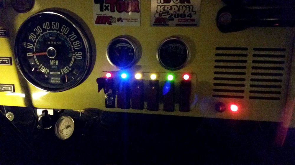
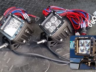
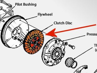
In most cases you will not simply be adding mood lights to your vehicle. More likely you will want these LED lights to act as indicators that tell you there is a circuit on, such as your Offroad lights, CB radio, a cooling fan or your onboard air compressor. To wire this circuit into your vehicle, you simply tap into the positive output power from the switch that drives your device (i.e., the offroad lights), into the longer, + side (anode) of the LED, then ground the resistor at the other end. So the power flows from the switch when it is flipped on, through the LED, through the resistor and to ground.
Calculating the Required Resistor
 The calculation used to find the value of the series resistor we need to know the diode forward voltage and current and its connections. This information can be obtained from the package if you purchased the LED.
In this example it is 2 volts and 20mA (0.02 amps).
The cathode lead is the one nearest a “flat” on the body.
Since the voltage across the diode (LED) is 2 volts and the battery voltage is 12 volts, then the voltage across the resistor is 12-2 = 10 volts.
The diode is in series with the resistor, so the current through then both is the same, 0.02 amps.
We now know the voltage across, and the current through the resistor.
From Ohm’s Law we can now calculate the value of the resistor.
Resistance = Volts divided by Amps = V/I = 10/0.02 =500 ohms.
Since this is not a standard value we can use a 470 or 560 ohm resistor as this application is not critical of values.
For a 4 volt (Blue or White LED) the formula would be:
Resistance = Volts divided by Amps = V/I = 8/0.02 =400 ohms.
The common 390 or 470 ohm resistor can be used for these.

your method of calculating the resistor is correct. However you are using the wrong voltage. You should be using the normal charging voltage of the system . some systems use 13.8v and some like GM use 14.2v. Some newer systems actually use voltages a few tenths even higher. While the LED’s will work , their lifespan can be considerably shorter at the incorrect voltage.
GREAT great info. Hard to find such info that is this clear. You guys seem to know you stuff and how to present it.
Thanks
Rick J