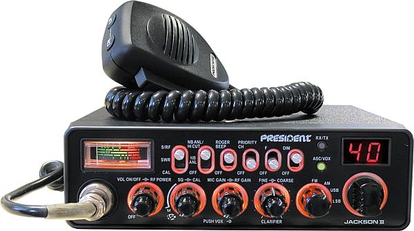

A Citizen Band or “CB” radio as it is widely known, is a radio transceiver for two way communication, transmitting and receiving, over a CB radio antenna. The job of the antenna on a CB radio system is two-fold. First it captures inbound radio-frequency signals which are then converted into electrical signals by the CB’s receiver. Second, it converts outbound electrical signals coming from the transmitter and converts them into radio-frequency signals that are then broadcasted onto the air waves, hopefully to another receiving CB radio. This is the transmitting function of a CB radio. It is during the transmitting function of a CB radio that proper tuning of the antenna becomes important.
This is due to the fact that an antenna is radiating radio-frequency signals of a specific wavelength. A properly tuned antenna will have a length that will accurately match the radio frequencies wavelength it is transmitting.
Determining the proper length of the antenna can be done using this formula:
Wavelength feet = 984 / frequency megahertz
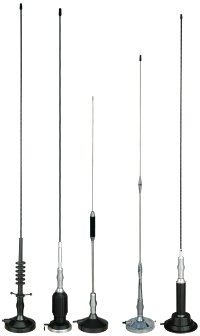
Citizens’ Band (CB) frequencies begin at 25.01 MHz. A full wavelength antenna would be slightly longer than 39.34 feet tall. For mobile purposes, the height of a full wavelength antenna would be impractical. So it is common practice to use antennas that are a fraction of the full wavelength. 1/8, 1/4, 5/8, and 1/2 are all commonly used wavelengths for antennas. For mobile CB antennas the quarter wave antenna is just under 10 feet long and take to form of the common whip antenna.
The dilemma is that there are 40 channels on today’s citizen band transceivers. Each channel is on a different frequency, thus requiring a different antenna length to exactly match each frequency. However, a separate antenna for each frequency is simply not practical so a compromise must be made and antenna manufacturers design antenna lengths from the middle of the CB’s 40 channel frequency range.
However with any compromise, there are tradeoffs and you have to adjust the Standing Wave Ratio or SWR of the antenna and wire until the SWR is acceptable. The antenna and antenna feed line have what is called characteristic impedance, or a measure of resistance to the current flow through the wire and out the antenna.
When a transmitter is connected to an antenna by a feed line, the impedance of the antenna and feed line must match exactly for maximum energy transfer from the feed line to the antenna to be possible.
In the best possible scenario, there would be a perfect match between antenna and the feed line where there would be a 100% conversion of electrical energy (sent from the CB to the antenna) into radio wave energy and radiated out into the atmosphere. When perfectly matched, the SWR measures 1:1 and the antenna is maximizing it’s potential output.
In the less than ideal scenario, a portion of the electrical energy (from the CB) is not converted into radio wave energy and instead is reflected back down the feed line and into the CB radio. This energy reflected back from the antenna creates standing waves of electrical energy in the antenna wire and in turn can cause damage to the radio circuitry.
When tuning the SWR of an antenna, an SWR meter is attached between the CB radio and the antenna feed line. SWR meters vary and some allow the meter to generate a signal on different channels while other SWR meters use the CB by keying up the microphone to generate a signal. As a signal is generated, the SWR meter is observed.
Ideally its best to tune your antenna for the channels that you use most if you typically only use one or a few channels. Otherwise use a  broader test across the full range of 40 channels. If the SWR never goes above 1.5:1, then your antenna is well tuned. If the SWR does go above 1.5:1, then test the SWR on the lower channels such as 1 through 5 and compare those SWR reading with the upper channels such as 35 through 40. If the SWR is greater on the lower channels then your antenna is too short and needs to be lengthened using the antennas height adjustment. Make small adjustments and retest. If the SWR is greater on the higher channels, then gradually shorten the antenna and retest with each small adjustment. When adjusting in either direction, if the SWR begins to test greater, reverse the adjustment to find the “sweet spot”.
Keep in mind that the electrical ground of the antenna, the shape of the vehicle including open doors, hoods and hatches as well as the location of the antenna on the vehicle, all play a part in proper adjustment. Test with the door and hatches closed and experiment with different mounting locations of the antenna.
Last, be sure to read and understand the instructions of the SWR meter as well as the antenna itself. In the end, with good SWR, you’ll be transmitting to your fullest potential and ensure longevity to your radio.